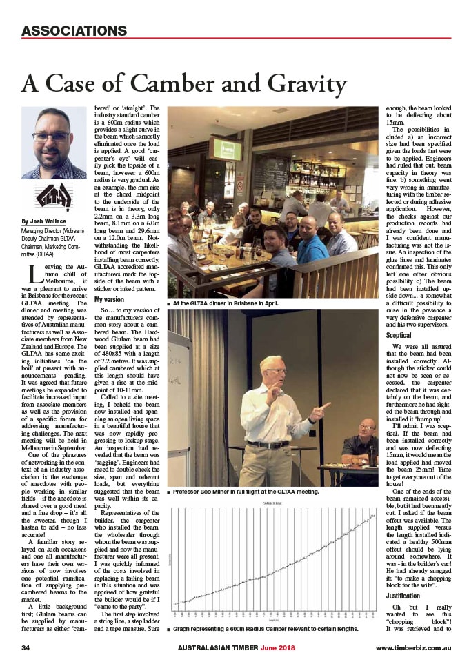
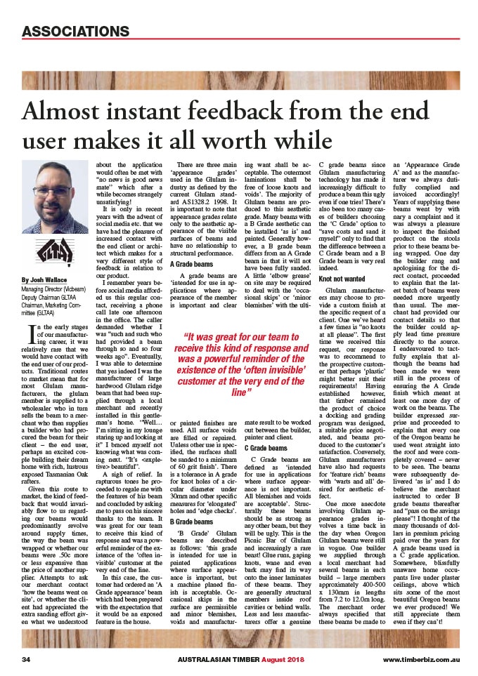
Leaving the Autumn chill of Melbourne, it was a pleasant to arrive in Brisbane for the recent GLTAA meeting. The dinner and meeting was attended by representatives of Australian manufacturers as well as Associate members from New Zealand and Europe. The GLTAA has some exciting initiatives ‘on the boil’ at present with announcements pending. It was agreed that future meetings be expanded to facilitate increased input from associate members as well as the provision of a specific forum for addressing manufacturing challenges. The next meeting will be held in Melbourne in September.
One of the pleasures of networking in the context of an industry association is the exchange of anecdotes with people working in similar fields – if the anecdote is shared over a good meal and a fine drop – it’s all the sweeter, though I hasten to add – no less accurate!
A familiar story relayed on such occasions and one all manufacturers have their own versions of now involves one potential ramification of supplying precambered beams to the market.
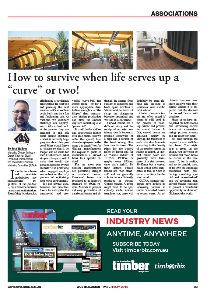
A little background first; Glulam beams can be supplied by manufacturers as either ‘cambered’ or ‘straight’. The industry standard camber is a 600m radius which provides a slight curve in the beam which is mostly eliminated once the load is applied. A good ‘carpenter’s eye’ will easily pick the topside of a beam, however a 600m radius is very gradual. As an example, the mm rise at the chord midpoint to the underside of the beam is in theory, only 2.2mm on a 3.3m long beam, 8.1mm on a 6.0m long beam and 29.6mm on a 12.0m beam. Notwithstanding the likelihood of most carpenters installing beam correctly, GLTAA accredited manufacturers mark the topside of the beam with a sticker or inked pattern.

My version
So… to my version of the manufacturers common story about a cambered beam. The Hardwood Glulam beam had been supplied at a size of 480×85 with a length of 7.2 metres. It was supplied cambered which at this length should have given a rise at the midpoint of 10-11mm. Called to a site meeting, I beheld the beam now installed and spanning an open living space in a beautiful house that was now rapidly progressing to lockup stage. An inspection had revealed that the beam was ‘sagging’. Engineers had raced to double check the size, span and relevant loads, but everything suggested that the beam was well within its capacity.
Representatives of the builder, the carpenter who installed the beam, the wholesaler through whom the beam was supplied and now the manufacturer were all present. I was quickly informed of the costs involved in replacing a failing beam in this situation and was apprised of how grateful the builder would be if I “came to the party”.
The first step involved a string line, a step ladder and a tape measure. Sure enough, the beam looked to be deflecting about 15mm.
The possibilities included a) an incorrect size had been specified given the loads that were to be applied. Engineers had ruled that out, beam capacity in theory was fine. b) something went very wrong in manufacturing with the timber selected or during adhesive application. However, the checks against our production records had already been done and I was confident manufacturing was not the issue. An inspection of the glue lines and laminates confirmed this. This only left one other obvious possibility c) The beam had been installed upside down… a somewhat a difficult possibility to raise in the presence a very defensive carpenter and his two supervisors.

Sceptical
We were all assured that the beam had been installed correctly. Although the sticker could not now be seen or accessed, the carpenter declared that it was certainly on the beam, and furthermore he had sighted the beam through and installed it ‘hump up’.
I’ll admit I was sceptical. If the beam had been installed correctly and was now deflecting 15mm, it would mean the load applied had moved the beam 25mm! Time to get everyone out of the house!
One of the ends of the beam remained accessible, but it had been neatly cut. I asked if the beam offcut was available. The length supplied versus the length installed indicated a healthy 500mm offcut should be lying around somewhere. It was – in the builder’s car! He had already snagged it; “to make a chopping block for the wife”.

Justification
Oh but I really wanted to see this “chopping block”! It was retrieved and to my delight, whilst one end had been cleanly cut with a power saw, the other end was untouched and still had hardened glue on the end from the factory floor. Manoeuvring the offcut in position, it was able to be lined up exactly with the end of the beam in situ – laminate for laminate, grain to grain, knot to knot… a perfect match.
Gravity did the rest. Our presses are configured vertically, meaning that when a beam is laid up laminate by laminate in the press, the laminates bow over the camber stick forming the gradual 600m radial arc. This also means that as the required pressure is slowly applied, a certain amount of glue is squeezed out and beads run down the end grain coagulating into goblets of glue which harden in position.
A group of us stood back. The glue runs told the story. Either gravity had been defied in my factory that day and I could now expect the men in black to swoop in or… the beam had indeed been installed upside down and the topside sticker surreptitiously removed after the fact. It was a sweet moment… I ducked outside “to make a phone call” leaving the carpenter to discuss with his supervisors the new reality of the situation which no longer needed to involve the manufacturer.
So, look out for those ‘topside stickers’ or ink patterns! Manufacturers under the GLTAA’s quality accreditation scheme will also have the GLTAA logo clearly marked on the topside of the beam providing extra reassurance.
